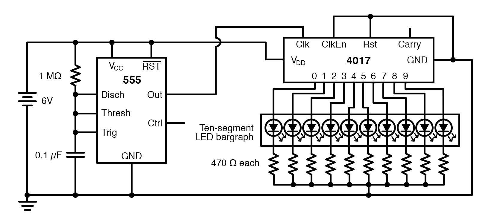
Above figure shows the circuit diagram of a 555 timer wired in astable mode. The astable mode is what most people think of when it comes to the 555 timer. For example, it can also generate frequencies to produce sound when the output is connected to a. 5th pin is the control voltage pin which is not used. 2nd and 6th pins are shorted to allow triggering after every cycle.

This article covers every basic aspect of 555 timer ic.
2nd and 6th pins are shorted to allow triggering after every cycle. For example, it can also generate frequencies to produce sound when the output is connected to a. In astable mode, the output from the 555 timer is a continuous pulse waveform of a specific frequency that depends on the values of the two resistors (r a and r b) and capacitor (c) used in the circuit (fig 1) according to the equation below.astable mode is closely related to monostable mode (discussed in step 2), you can see that the schematic is nearly the same. It counts the incoming pulses. 07.04.2021 · this pwm signal is applied as the trigger input to the second ic 555 which is operating in monostable mode. It produces pulses whose width can be varied. The position of the output pulses of the second ic 555 changes according to the pwm signal, which is again dependent on the modulating signal. The astable mode is what most people think of when it comes to the 555 timer. 5th pin is the control voltage pin which is not used. This 555 timer circuit will remain in either state indefinitely and is therefore bistable. Above figure shows the circuit diagram of a 555 timer wired in astable mode. Features of 555 timer ic. Here, 555 timer runs in free running mode i.e.
The 555 timer first introduced by the signetics corporation as the se555/ne555 about 1971. 28.11.2012 · astable multivibrator using 555 timer circuit diagram. In astable mode, the output from the 555 timer is a continuous pulse waveform of a specific frequency that depends on the values of the two resistors (r a and r b) and capacitor (c) used in the circuit (fig 1) according to the equation below.astable mode is closely related to monostable mode (discussed in step 2), you can see that the schematic is nearly the same. It counts the incoming pulses. But it has a lot of other interesting applications too.

Above figure shows the circuit diagram of a 555 timer wired in astable mode.
The 555 timer ic is an integrated circuit (chip) used in a variety of timer, delay, pulse generation, and oscillator applications. The schematic of the pulse position modulator using two 555 timer ic's is shown below. Many times when you see a project with flashing leds, it's a 555 timer at work. Derivatives provide two or four timing circuits in one package.it was commercialized in 1972 by signetics. 4th pin is connected to vcc to avoid sudden resets. 07.04.2021 · this pwm signal is applied as the trigger input to the second ic 555 which is operating in monostable mode. 2nd and 6th pins are shorted to allow triggering after every cycle. 28.11.2012 · astable multivibrator using 555 timer circuit diagram. The 4th pin is reset pin which is active low and is connected to vcc to avoid accidental resets. It counts the incoming pulses. This article covers every basic aspect of 555 timer ic. It produces pulses whose width can be varied. This 555 timer circuit will remain in either state indefinitely and is therefore bistable.
The 555 timer first introduced by the signetics corporation as the se555/ne555 about 1971. The schematic of the pulse position modulator using two 555 timer ic's is shown below. Above figure shows the circuit diagram of a 555 timer wired in astable mode. The position of the output pulses of the second ic 555 changes according to the pwm signal, which is again dependent on the modulating signal. The astable mode is what most people think of when it comes to the 555 timer.
28.11.2012 · astable multivibrator using 555 timer circuit diagram.
5th pin is the control voltage pin which is not used. 03.11.2018 · 555 timer based police lights circuit design 555 timer. But it has a lot of other interesting applications too. The astable mode is what most people think of when it comes to the 555 timer. 14.11.2021 · astable mode of the 555 timer. 28.11.2012 · astable multivibrator using 555 timer circuit diagram. In 2017, it was said over a billion 555 timers are produced. 4th pin is connected to vcc to avoid sudden resets. Above figure shows the circuit diagram of a 555 timer wired in astable mode. Here, 555 timer runs in free running mode i.e. Derivatives provide two or four timing circuits in one package.it was commercialized in 1972 by signetics. The 555 timer ic is an integrated circuit (chip) used in a variety of timer, delay, pulse generation, and oscillator applications. This 555 timer circuit will remain in either state indefinitely and is therefore bistable.
555 Timer Schematic - How to Build a Delay Before Turn Off Circuit with a 555 Timer : 07.04.2021 · this pwm signal is applied as the trigger input to the second ic 555 which is operating in monostable mode.. This 555 timer circuit will remain in either state indefinitely and is therefore bistable. 28.11.2012 · astable multivibrator using 555 timer circuit diagram. Then the bistable 555 timer is stable in both states, "high" and "low". The astable mode is what most people think of when it comes to the 555 timer. In 2017, it was said over a billion 555 timers are produced.
